Nissan Rogue Service Manual: Valve timing control
Exploded View

- Valve timing cover
- 2. O-rings
- Intake valve timing intermediate lock control solenoid valve
- Intake valve timing control solenoid valve
- Exhaust valve timing control solenoid valve
Intake Valve Timing Intermediate Lock Control Solenoid Valve, Intake Valve Timing Control Solenoid Valve, and Exhaust Valve Timing Control Solenoid Valve
REMOVAL
- Disconnect the battery negative terminal. Refer to PG-75, "Exploded View"
- Remove cowl top extension. Refer to EXT-25, "Removal and Installation".
- Remove the RH engine mount torque rod. Refer to EM-81, "Exploded View".
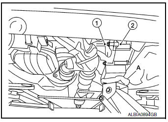
- Use a suitable jack (A) to securely support the bottom of the engine (1) and the transaxle assembly (2).
CAUTION: Put a piece of wood or an equivalent as the supporting surface and secure in a stable condition.
- Remove A/C line bracket bolt.
- Remove harness grounds from engine mounting bracket (RH).
- Remove harness retainers from engine mounting bracket (RH).
- Remove the engine mounting bracket (RH). Refer to EM-81, "Exploded View"
- Remove the RH engine mounting support bracket. Refer to EM-81, "Exploded View".
- Remove the RH engine mount torque rod. Refer to EM-81, "Exploded View".
- Disconnect harness connectors from intake valve timing intermediate lock control solenoid valve, intake valve timing control solenoid valve, and exhaust valve timing control solenoid valve connectors.
- Remove intake valve timing intermediate lock control solenoid valve, intake valve timing control solenoid valve, and exhaust valve timing control solenoid valve bolts.
- Remove intake valve timing intermediate lock control solenoid valve, intake valve timing control solenoid valve, exhaust valve timing control solenoid valve from valve timing control cover.
- . Remove O-rings from intake valve timing intermediate lock control solenoid valve, intake valve timing control solenoid valve, and exhaust valve timing control solenoid valve.
INSTALLATION
Installation is in the reverse order of removal.
CAUTION:
- Do not reuse O-rings.
- Lubricate O-rings with clean engine oil before installing.
Valve Timing Control Cover
REMOVAL
- Remove the intake valve timing intermediate lock control solenoid valve, intake valve timing control solenoid valve, exhaust valve timing control solenoid valve. Refer to EM-74, "Intake Valve Timing Intermediate Lock Control Solenoid Valve, Intake Valve Timing Control Solenoid Valve, and Exhaust Valve Timing Control Solenoid Valve".
- Remove harness grounds and retainers from the top if the engine mount bracket.
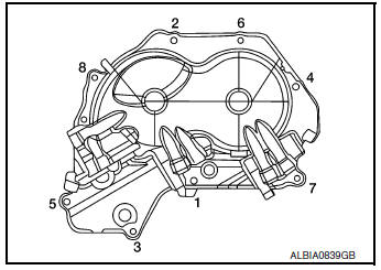
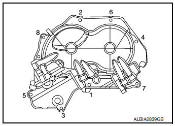
- Loosen the valve timing control cover bolts in the reverse order shown.
- Remove the valve timing control cover bolts.
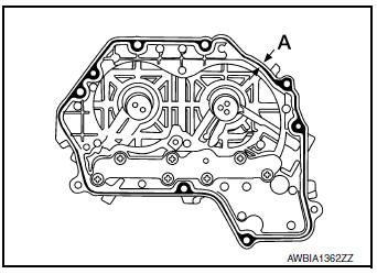
- Remove the valve timing control cover by cutting the liquid gasket using Tool (A).
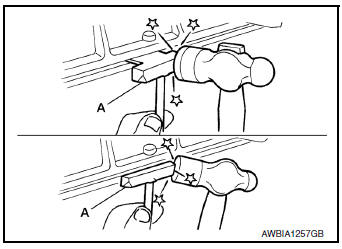
Tool number : KV10111100 (J-37228)
NOTE: Do not loosen screws (A) on the back of the valve timing control cover.
INSTALLATION
- Install valve timing control cover with the following procedure.
- Install intake valve timing intermediate lock control solenoid valve, intake valve timing control solenoid valve and exhaust valve timing control solenoid valve to valve timing control cover.
- Install O-ring to front cover side.
CAUTION: Do not reuse O-ring.
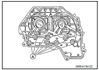
- Apply liquid gasket to the positions shown. Refer to GI-22, "Recommended Chemical Products and Sealants".
Diameter (A) : 3.4 - 4.4 mm (0.134 - 0.173 in)
- Install valve timing control cover.
- Tighten the bolts to specification in the numerical order shown.
 Camshaft
Exploded View
Camshaft position sensor (INT)
O-ring
Camshaft brackets (INT)
Camshaft brackets (EXH)
Camshaft (INT)
O-ring
Camshaft bracket (No. 1)
Camshaft sproc ...
 Oil seal
VALVE OIL SEAL
VALVE OIL SEAL : Removal and Installation
REMOVAL
Remove camshafts. Refer to EM-64, "Removal and Installation".
Remove valve lifters. Refer to EM-56, " ...
Other materials:
Intake manifold
Exploded View
Intake manifold
Intake manifold gasket
Electirc throttle control actuator O-ring
Electric throttle control actuator
Removal and Installation
REMOVAL
WARNING:
To avoid danger of being scalded, do not drain engine coolant when engine is
hot.
N ...
Towing recommended by NISSAN
All-Wheel Drive (AWD) models
NISSAN recommends that towing dollies be
used when towing your vehicle or the vehicle be
placed on a flatbed truck as illustrated.
CAUTIONDO NOT tow AWD models with any of the
wheels on the ground as this may cause
serious and expensive damage to the ...
Engine control system
Symptom Table
SYSTEM — BASIC ENGINE CONTROL SYSTEM
1 - 6: The numbers refer to the order of inspection.
(continued on next table)
SYSTEM — ENGINE MECHANICAL & OTHER
1 - 6: The numbers refer to the order of inspection. ...
