Nissan Rogue Service Manual: Special Cautions to Ensure the Safe Disposal of Sodium-filled Exhaust Valves
Handling and disposal of sodium-filled exhaust valves requires special care and consideration. Under conditions such as breakage with subsequent contact with water, metal sodium which lines the inner portion of exhaust valve will react violently, forming sodium hydroxide and hydrogen which may result in an explosion. Sodium-filled exhaust valve is identified on the top of its stem as shown in illustration.
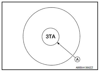
(A) : Identification mark of sodium-filled exhaust valve
DEALER DISPOSAL INSTRUCTIONS
CAUTION:
- Use approved shatter-resistant eye protection when performing this procedure.
- Perform this and all subsequent disposal work procedures in an open room, away from flammable liquids. Keep a fire extinguisher, rated at least 10 ABC, in close proximity to the work area.
- Be sure to wear rubber gloves when performing the following operations.
- Make sure the resultant (high alkalinity) waste water does not contact your skin. If the waste water does contact you, wash the contacted area immediately with large quantities of water.
- Dealers should check their respective state and local regulations concerning any chemical treatment or waste water discharge permits which may be required to dispose of the resultant (high alkalinity) waste water.
- Clamp valve stem in a vice.
- The valve has a specially-hardened surface. To cut through it, first remove a half-round section, approximately 30 mm (1.18 in) long using air-powered grinder until black color is removed and silver color appears.

(A) : Black color
(B) : Silver color
(c) : 47 mm (1.85 in)
(d) : 17 mm (0.67 in)
- Use hacksaw to cut through approximately half the diameter of valve stem. Make the serration at a point 40 mm (1.57 in) from the end of valve stem.
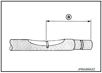
(a) : 40 mm (1.57 in)

- Cover the serrated end of the valve with a large shop towel (A).
Strike the valve face end with a hammer, separating it into two pieces.
- Fill a bucket, such as a 20
 (5-1/4 US gal, 4-3/8 Imp gal)
oil
can, with at least 10
(5-1/4 US gal, 4-3/8 Imp gal)
oil
can, with at least 10  (2-5/8 US
gal, 2-1/4 lmp gal) of water.
(2-5/8 US
gal, 2-1/4 lmp gal) of water.Carefully place the already cut (serrated) valves into the water one-at-a-time using a set of large tweezers and quickly move away at least 2.7 m (9 ft).
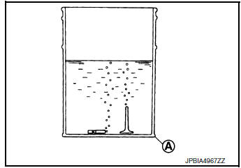
- The valves should be placed in a standing position as shown in
the illustration to allow complete reaction. After the bubbling
action has subsided, additional valves can be placed into the
bucket allowing each subsequent chemical reaction to subside.
However, no more than 8 valves should be placed in the same 10
(2-5/8 US gal, 2-1/4 lmp
gal) amount of water. The complete
chemical reaction may take as long as 4 to 5 hours.Remove the valves using a set of large tweezers after the chemical reaction has stopped. Afterwards, valves can be disposed as ordinary scrap.
A : Bucket [Such as 20 (5-1/4 US gal, 4-3/8 Imp gal) oil can]
 Precaution
Precaution for Supplemental Restraint System
(SRS) "AIR BAG" and "SEAT BELT PRE-TENSIONER"
The Supplemental Restraint System such as “AIR BAG” and “SEAT BELT PRE-TENSIONERâ ...
 Liquid Gasket
REMOVAL OF LIQUID GASKET SEALING
After removing the bolts and nuts, separate the mating surface and
remove the liquid gasket using Tool (A).
Tool Number : KV10111100 (J-37228)
CAUTION:
Be c ...
Other materials:
B terminal circuit
Description
“B” terminal circuit supplies power to charge the battery and to operate the
vehicles electrical system.
Diagnosis Procedure
Regarding Wiring Diagram information. Refer to CHG-7, "Wiring Diagram".
1.CHECK “B” TERMINAL CONNECTION
Turn ignition switch OFF. ...
Removal and installation
AV CONTROL UNIT
Exploded View
AV control unit bracket (LH)
AV control unit
AV control unit bracket (RH)
Removal and Installation
REMOVAL
CAUTION:
Before disconnecting the AV control unit and battery terminals,
turn the ignition switch OFF and wait
at least 30 secon ...
Automatic operation
Cooling and/or dehumidified heating
(AUTO)
This mode may be used all year round as the
system automatically works to keep a constant
temperature. Air flow distribution and fan speed
are also controlled automatically.
Press the AUTO button on. The indicator on
the button will illumin ...
