Nissan Rogue Service Manual: Removal and installation
ACCELERATOR PEDAL ASSEMBLY
Exploded View

- Brake pedal
- Accelerator pedal assembly
- Locator hook
- Locator pin
- Bolt
Removal and Installation
REMOVAL
- Disconnect the harness connector from the accelerator pedal assembly.
- Remove the bolts, then remove accelerator pedal assembly.
CAUTION:
- Do not disassemble accelerator pedal assembly.
- Do not drop or impact accelerator pedal assembly.
- Do not expose accelerator pedal assembly to water.
INSTALLATION
Installation is in the reverse order of removal.
NOTE: When installing the accelerator pedal assembly, make sure to align locator hook and locator pin before installing bolts.
For inspection, refer to ACC-3, "Inspection".
Inspection
INSPECTION AFTER INSTALLATION
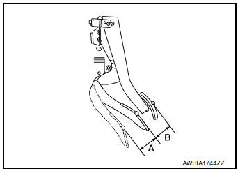
- Check that the accelerator pedal moves smoothly within the specified range.
Accelerator pedal stroke (A) : Refer to ACC-5, "Accelerator Control"
- Check the accelerator pedal height.
Accelerator pedal height (B) : Refer to ACC-5, "Accelerator Control"
- accelerator pedal does not meet specified values, check brake pedal height. Refer to ACC-3, "Inspection".
- Depress and release the accelerator pedal to check that it returns quickly and smoothly to the original released position.
CAUTION:
- Whenever the harness connector of the accelerator pedal position sensor has been disconnected, perform "Accelerator Pedal Released Position Learning". Refer to EC-139, "Work Procedure".
- The accelerator pedal should operate smoothly without catching when the pedal operating force is released. The pedal should return smoothly to the fully raised position. The spring should be free from damage.
 Precaution
Precaution for Supplemental Restraint System (SRS) "AIR BAG" and "SEAT
BELT
PRE-TENSIONER"
The Supplemental Restraint System such as ŌĆ£AIR BAGŌĆØ and ŌĆ£SEAT BELT PRE-TENSIONE ...
 Service data and specifications
(SDS)
Service data and specifications
(SDS)
Accelerator Control
Accelerator pedal stroke (A)
49.6 - 52.4 (1.95 - 2.06
Pedal height difference between accelerator and brake (B)
35 - 45 (1.38 - 1.77)
...
Other materials:
P1226 TP sensor
DTC Description
DTC DETECTION LOGIC
DTC No.
CONSULT screen terms
(Trouble diagnosis content)
DTC detecting condition
P1226
CTP LEARNING-B1
(CTP LEARNING-B1)
Closed throttle position learning is not performed successfully,
repeatedly
POSSIBLE CAUSE
Elect ...
Floor trim
Exploded View
Rear floor trim (with third row
seat)
Rear floor trim (without third
row seat)
Floor trim hook
Front floor trim
Front floor spacer (RH)
Front floor spacer (LH)
Rear floor spacer (LH)
Rear floor spacer (RH)
Third row floor spacer (LH)
...
P0778 pressure control solenoid B
DTC Description
DTC DETECTION LOGIC
DTC
CONSULT screen terms
(Trouble diagnosis content)
DTC detection condition
P0778
PC SOLENOID B
(Pressure Control Solenoid ŌĆ£BŌĆØ Electrical)
When all of the following conditions are satisfied and this state is
maintained
...
