Nissan Rogue Service Manual: Rear window defogger and door mirror defogger do not operate
Diagnosis Procedure
Regarding Wiring Diagram information, refer to DEF-12, "Wiring Diagram".
1. CHECK REAR WINDOW DEFOGGER SWITCH
Check rear window defogger switch.
Refer to DEF-22, "WITH MANUAL A/C : Component Function Check".
Is the inspection result normal? YES >> GO TO 2.
NO >> Repair or replace the malfunctioning parts.
2. CHECK REAR WINDOW DEFOGGER RELAY
Check rear window defogger relay.
Refer to DEF-24, "Component Function Check".
Is the inspection result normal? YES >> GO TO 3.
NO >> Repair or replace the malfunctioning parts.
3. CHECK REAR WINDOW DEFOGGER POWER SUPPLY AND GROUND CIRCUIT
Check rear window defogger power supply and ground circuit.
Refer to DEF-26, "Component Function Check".
Is the inspection result normal? YES >> GO TO 4.
NO >> Repair or replace the malfunctioning parts.
4. CHECK DOOR MIRROR DEFOGGER POWER SUPPLY
- Turn ignition switch ON.
- Check voltage between fuse block (J/B) connector and ground.
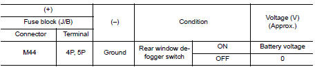
Is the inspection result normal? YES >> GO TO 5.
NO >> Replace fuse block (J/B).
5. CHECK BOTH DOOR MIRROR DEFOGGER
- Check door mirror LH. Refer to DEF-28, "Component Function Check".
- Check door mirror RH. Refer to DEF-30, "Component Function Check".
Is the inspection result normal? YES >> Check intermittent incident. Refer to GI-41, "Intermittent Incident".
NO >> Repair or replace the malfunctioning parts.
 Defogger system symptoms
Symptom Table
*:if equipped ...
 Rear window defogger does not operate but both of door mirror defogger
operate
Rear window defogger does not operate but both of door mirror defogger
operate
Diagnosis Procedure
1. CHECK REAR WINDOW DEFOGGER POWER SUPPLY AND GROUND CIRCUIT
Check rear window defogger power supply and ground circuit.
Refer to DEF-26, "Component Function Check" ...
Other materials:
C1607, C1608 EPS control unit
DTC Logic
DTC DETECTION LOGIC
DTC
Display item
Malfunction detected condition
Possible cause
C1607
EEPROM
When the memory (EEPROM) system malfunction is
detected in EPS control unit.
EPS control unit
C1608
CONTROL UNIT
When the in ...
Removal and installation
FRONT CAMERA
Exploded View
Front grille
Front camera
Removal and Installation
REMOVAL
Remove the front grille. Refer to EXT-23, "Removal and
Installation".
Remove screws and front camera.
INSTALLATION
Installation is in the reverse order of re ...
Troubleshooting guide
Verify the location of all Intelligent Keys that are
programmed for the vehicle. If another Intelligent
Key is in range or inside the vehicle, the vehicle
system may respond differently than expected.
Symptom
Possible Cause
Remedy
When stopping the engine
The Shift to Pa ...
