Nissan Rogue Service Manual: Preparation
PREPARATION
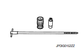
Special Service Tool
The actual shape of the tools may differ from those illustrated here.
|
Tool number (TechMate No.) Tool name |
Description |
|
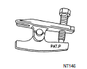
| KV40107300 ( ÔÇö ) Boot band crimping tool |
|
Installing boot band |
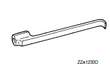
| KV40107500 ( ÔÇö ) Drive shaft attachment |
|
Removing drive shaft |
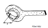
| KV38107900 ( ÔÇö ) Protector |
|
Installing drive shaft a: 32 mm (1.26 in) dia. |
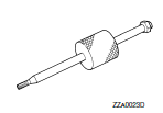
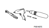
Commercial Service Tools
|
Tool name |
Description |
|
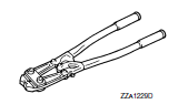
| Ball joint remover |
|
Removing wheel stud |
| Drive shaft puller |
|
Removing drive shaft joint sub ass |
| Sliding hammer |
|
Removing drive shaft |
| Power tool |
|
Loosening nuts, screws and bolts |
 Precaution
Precaution for supplemental restraint system (srs) "air bag" and "seat
belt
pre-tensioner"
The Supplemental Restraint System such as ÔÇťAIR BAGÔÇŁ and ÔÇťSEAT BELT PRE-TENSIONE ...
 Symptom diagnosis
NOISE, VIBRATION AND HARSHNESS (NVH) TROUBLESHOO
NVH Troubleshooting Chart
Use chart below to find the cause of the symptom. If necessary, repair or
replace these parts.
├Ś: Applicable ...
Other materials:
Lifting point
Special service tool
The actual shapes of Kent-Moore tools may differ from those of special
service tools illustrated here.
Tool number
(Kent-Moore No.)
Tool name
Description
LM4086-0200
( - )
Board on attachment
LM4519-0000
( - )
Safety stan ...
Precaution
Precaution for Supplemental Restraint System (SRS) "AIR BAG" and "SEAT
BELT
PRE-TENSIONER"
The Supplemental Restraint System such as ÔÇťAIR BAGÔÇŁ and ÔÇťSEAT BELT PRE-TENSIONERÔÇŁ,
used along
with a front seat belt, helps to reduce the risk or severity of injury to the
...
Symptom diagnosis
NISSAN VEHICLE IMMOBILIZER SYSTEM-NATS SYMPTOMS
Symptom Table
NOTE:
Before performing the diagnosis in the following table, check
ÔÇťSEC-150, "Work Flow"ÔÇŁ.
Check that vehicle is under the condition shown in ÔÇťConditions
of vehicleÔÇŁ before starting diagnosis, ...
