Nissan Rogue Service Manual: P2765 input speed sensor B
DTC Description
DTC DETECTION LOGIC
| DTC | CONSULT screen terms (Trouble diagnosis content) | DTC detection condition |
| P2765 | INPUT SPEED SENSOR B (Input/Turbine Speed Sensor B Circuit) | When 1 is satisfied and any of 2, 3 or 4 is satisfied and this state
is maintained
for 5 seconds:
|
POSSIBLE CAUSE
- Harness or connector (Output speed sensor circuit is open or shorted)
- Output speed sensor
FAIL-SAFE
- Start is slow
- Acceleration is slow
- Lock-up is not performed
DTC CONFIRMATION PROCEDURE
CAUTION: Be careful of the driving speed.
1.PREPARATION BEFORE WORK
If another "DTC CONFIRMATION PROCEDURE" occurs just before, turn ignition switch OFF and wait for at least 10 seconds, then perform the next test.
>> GO TO 2.
2.CHECK DTC DETECTION
- Start the engine.
- Drive the vehicle.
- Maintain the following conditions for 10 seconds or more.
Selector lever : “D” position
Engine speed : 1,200 rpm or more
Vehicle speed : 55 km/h (34 MPH) or more
- Stop the vehicle.
- Check the first trip DTC.
Is “P2765” detected? YES >> Go to TM-168, "Diagnosis Procedure".
NO-1 >> To check malfunction symptom before repair: Refer to GI-41, "Intermittent Incident".
NO-2 >> Confirmation after repair: INSPECTION END
Diagnosis Procedure
1.CHECK OUTPUT SPEED SENSOR POWER CIRCUIT
- Turn ignition switch OFF.
- Disconnect output speed sensor connector.
- Turn ignition switch ON.
- Check voltage between output speed sensor harness connector terminal and ground.
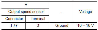
Is the inspection result normal? YES >> GO TO 2.
NO >> GO TO 6.
2.CHECK OUTPUT SPEED SENSOR GROUND CIRCUIT
Check continuity between output speed sensor harness connector terminal and ground.

Is the inspection result normal? YES >> GO TO 3.
NO >> Repair or replace malfunctioning parts.
3.CHECK CIRCUIT BETWEEN OUTPUT SPEED SENSOR AND TCM (PART 1)
- Turn ignition switch OFF.
- Disconnect TCM connector.
- Check continuity between output speed sensor harness connector terminal and TCM harness connector terminal.

Is the inspection result normal? YES >> GO TO 4.
NO >> Repair or replace malfunctioning parts.
4.CHECK CIRCUIT BETWEEN OUTPUT SPEED SENSOR AND TCM (PART 2)
Check continuity between output speed sensor harness connector terminal and ground.

Is the inspection result normal? YES >> GO TO 5.
NO >> Repair or replace malfunctioning parts.
5.CHECK TCM INPUT SIGNALS
- Connect all of disconnected connectors.
- Lift the vehicle.
- Start the engine.
- Check frequency of output speed sensor.
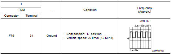
Is the inspection result normal? YES >> INSPECTION END
NO >> Replace output speed sensor. Refer to TM-209, "Removal and Installation".
6.CHECK CIRCUIT BETWEEN IPDM E/R AND OUTPUT SPEED SENSOR
- Turn ignition switch OFF.
- Disconnect IPDM E/R connector.
- Check continuity between IPDM E/R harness connector terminal and output speed sensor harness connector terminals.
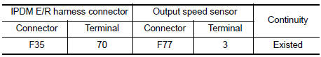
Is the check result normal? YES >> GO TO 7.
NO >> Repair or replace malfunctioning parts.
7.DETECT MALFUNCTIONING ITEMS
Check the following items:
- Open circuit or short circuit in harness between ignition switch and IPDM E/R. Refer to PG-15, "Wiring Diagram — Ignition Power Supply —".
- Short circuit in harness between IPDM E/R harness connector terminal 70 and output speed sensor harness connector terminal 3.
- 10A fuse (No.46, located in the IPDM E/R). Refer to PG-68, "IPDM E/R Terminal Arrangement".
- IPDM E/R
Is the check result normal? YES >> INSPECTION END
NO >> Repair or replace malfunctioning parts.
 P0967 pressure control solenoid B
DTC Description
DTC DETECTION LOGIC
DTC
CONSULT screen terms
(Trouble diagnosis content)
DTC detection condition
P0967
PC SOLENOID B
(Pressure Control Solenoid B Contr ...
 P2813 select solenoid
DTC Description
DTC DETECTION LOGIC
DTC
CONSULT screen terms
(Trouble diagnosis content)
DTC detection condition
P2813
SELECT SOLENOID
(Select solenoid)
When any of ...
Other materials:
U0101 CAN comm circuit
Description
CAN (Controller Area Network) is a serial communication line for real time
application. It is an on-vehicle multiplex
communication line with high data communication speed and excellent error
detection ability. Many electronic
control units are equipped onto a vehicle, and each co ...
Center console assembly
Exploded View
Center console cup holder (without
heated seats)
Coin tray insert
Center console cup holder (with
heated seats)
Front heated seat switch (RH)
Front heated seat switch (LH)
Shift selector finisher
Shift selector finisher mat
Center console side ...
U1111 lost communication (chassis control module)
DTC Description
DTC DETECTION LOGIC
DTC
CONSULT screen terms
(Trouble diagnosis content)
DTC detection condition
U1111
LOST COMM (CHASSIS CONT MDUL)
(Lost Communication With Chassis Control
Module)
When the ignition switch is ON, TCM is unable to receive the CA ...
