
Nissan Rogue Service Manual: P0420 three way catalyst function
DTC Description
DTC DETECTION LOGIC
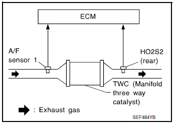
The ECM monitors the switching frequency ratio of air fuel ratio (A/F) sensor 1 and heated oxygen sensor 2.
A three way catalyst (manifold) with high oxygen storage capacity will indicate a low switching frequency of heated oxygen sensor 2.
As oxygen storage capacity decreases, the heated oxygen sensor 2 switching frequency will increase.
When the frequency ratio of air fuel ratio (A/F) sensor 1 and heated oxygen sensor 2 approaches a specified limit value, the three way catalyst (manifold) malfunction is diagnosed.
| DTC No. | CONSULT screen terms (Trouble diagnosis content) | DTC detecting conditio |
| P0420 | TW CATALYST SYS-B1 (Catalyst system efficiency below threshold bank 1) |
|
POSSIBLE CAUSE
- Three way catalyst (manifold)
- Exhaust tube
- Intake air leaks
- Fuel injector
- Fuel injector leaks
- Spark plug
- Improper ignition timing
FAIL-SAFE
Not applicable
DTC CONFIRMATION PROCEDURE
1.PRECONDITIONING
If DTC Confirmation Procedure has been previously conducted, always perform the following procedure before conducting the next test.
- Turn ignition switch OFF and wait at least 10 seconds.
- Turn ignition switch ON.
- Turn ignition switch OFF and wait at least 10 seconds.
Will CONSULT be used? YES >> GO TO 2.
NO >> GO TO 6.
2.PERFORM DTC CONFIRMATION PROCEDURE-1
 With CONSULT
TESTING CONDITION: Do not hold engine speed for more than the specified minutes below.
- Start engine and warm it up to the normal operating temperature.
- Turn ignition switch OFF and wait at least 10 seconds.
- Turn ignition switch ON.
- Turn ignition switch OFF and wait at least 10 seconds.
- Start engine and keep the engine speed between 3,500 and 4,000 rpm for at least 1 minute under no load.
- Let engine idle for 1 minute.
- Select “DATA MONITOR� mode of “ENGINE� using CONSULT.
- Check that “COOLAN TEMP/S� indicates more than 70°C (158°F). If not, warm up engine and go to next step when “COOLAN TEMP/S� indication reaches to 70°C (158°F).
- Open engine hood.
- Select “DTC & SRT CONFIRMATION� then “SRT WORK SUPPORT� mode of “ENGINE� using CONSULT.
- Rev engine up to 2,500 to 3,000 rpm and hold it for 3 consecutive minutes then release the accelerator pedal completely.
- Check the indication of “CATALYST�.
Which is displayed on CONSULT screen? CMPLT>> GO TO 5.
INCMP >> GO TO 3.
3.PERFORM DTC CONFIRMATION PROCEDURE-2
- Wait 5 seconds at idle.
- Rev engine up to 2,500 to 3,000 rpm and maintain it until “INCMP� of “CATALYST� changes to “CMPLT� (It will take approximately 5 minutes).
Does the indication change to “CMPLT�?
YES >> GO TO 5.
NO >> GO TO 4.
4.PERFORM DTC CONFIRMATION PROCEDURE AGAIN
- Stop engine and cool it down to less than 70°C (158°F).
- Perform DTC confirmation procedure again.
>> GO TO 2.
5.PERFORM DTC CONFIRMATION PROCEDURE-3
Check 1st trip DTC.
Is 1st trip DTC detected? YES >> Proceed to EC-302, "Diagnosis Procedure".
NO >> INSPECTION END
6.PERFORM COMPONENT FUNCTION CHECK
 Without CONSULT
- Start engine and warm it up to the normal operating temperature.
- Turn ignition switch OFF and wait at least 10 seconds.
- Restart engine and keep the engine speed between 3,500 and 4,000 rpm for at least 1 minute under no load.
- Let engine idle for 1 minute.
- Open engine hood.
- Check the voltage between ECM harness connector terminals as per the following condition.
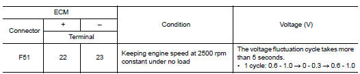
Is the inspection result normal? YES >> INSPECTION END
NO >> Proceed to EC-302, "Diagnosis Procedure".
Diagnosis Procedure
1.CHECK EXHAUST SYSTEM
Visually check exhaust tubes and muffler for dent.
Is the inspection result normal?
YES >> GO TO 2.
NO >> Repair or replace error-detected parts.
2.CHECK EXHAUST GAS LEAK
- Start engine and run it at idle.
- Listen for an exhaust gas leak before the three way catalyst (manifold).
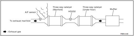
Is exhaust gas leak detected? YES >> Repair or replace error-detected parts.
NO >> GO TO 3.
3.CHECK INTAKE AIR LEAK
Listen for an intake air leak after the mass air flow sensor.
Is intake air leak detected? YES >> Repair or replace error-detected parts.
NO >> GO TO 4.
4.CHECK IGNITION TIMING AND IDLE SPEED
Check the following items. Refer to EC-132, "Work Procedure".
For specification, refer to EC-500, "Ignition Timing" For specification, refer to EC-500, "Idle Speed".
Is the inspection result normal? YES >> GO TO 5.
NO >> Follow the EC-132, "Work Procedure".
5.CHECK FUEL INJECTOR
Check the fuel injector. Refer to EC-464, "Component Function Check".
Is the inspection result normal? YES >> GO TO 6.
NO >> Perform EC-464, "Diagnosis Procedure".
6.CHECK FUNCTION OF IGNITION COIL-1
CAUTION: Do the following procedure in the place where ventilation is good without the combustible.
- Turn ignition switch OFF.
- Remove fuel pump fuse in IPDM E/R to release fuel pressure.
NOTE: Do not use CONSULT to release fuel pressure, or fuel pressure applies again during the following procedure.
- Start engine.
- After engine stalls, crank it two or three times to release all fuel pressure.
- Turn ignition switch OFF.
- Remove all ignition coil harness connectors to avoid the electrical discharge from the ignition coils.
- Remove ignition coil and spark plug of the cylinder to be checked.
- Crank engine for 5 seconds or more to remove combustion gas in the cylinder.
- Connect spark plug and harness connector to ignition coil.
- Fix ignition coil using a rope etc. with gap of 13 - 17 mm (0.52 - 0.66 in) between the edge of the spark plug and grounded metal portion as shown in the figure.
- Crank engine for about 3 seconds, and check whether spark is generated between the spark plug and the grounded metal portion.
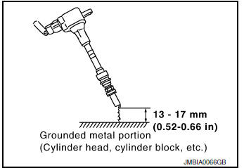
Spark should be generated.
CAUTION:
- Do not approach to the spark plug and the ignition coil within 50 cm (19.7 in). Be careful not to get an electrical shock while checking, because the electrical discharge voltage becomes 20 kV or more.
- It might cause to damage the ignition coil if the gap of more than 17 mm (0.66 in) is taken.
NOTE: When the gap is less than 13 mm (0.52 in), the spark might be generated even if the coil is malfunctioning.
Is the inspection result normal? YES >> GO TO 10.
NO >> GO TO 7.
7.CHECK FUNCTION OF IGNITION COIL-2
- Turn ignition switch OFF.
- Disconnect spark plug and connect a known-good spark plug.
- Crank engine for about 3 seconds, and recheck whether spark is generated between the spark plug and the grounded metal portion.
Spark should be generated.
Is the inspection result normal? YES >> GO TO 8.
NO >> Check ignition coil, power transistor and their circuits. Refer to EC-470, "Diagnosis Procedure".
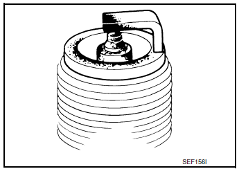
8.CHECK SPARK PLUG
Check the initial spark plug for fouling, etc. Refer to EM-17, "Removal and Installation".
Is the inspection result normal? YES >> Replace spark plug(s) with standard type one(s). For spark plug type, refer to EM-115, "General Specification".
NO >> Repair or clean spark plug. Refer to EM-17, "Removal and Installation". Then GO TO 9
9.CHECK FUNCTION OF IGNITION COIL-3
- Reconnect the initial spark plugs.
- Crank engine for about 3 seconds, and recheck whether spark is generated between the spark plug and the grounded portion.
Spark should be generated.
Is the inspection result normal? YES >> INSPECTION END
NO >> Replace spark plug(s) with standard type one(s). For spark plug type, refer to EM-115, "General Specification".
10.CHECK FUEL INJECTOR
- Turn ignition switch OFF.
- Remove fuel injector assembly.
Refer to EM-40, "Exploded View".
Keep fuel hose and all fuel injectors connected to fuel tube.
- Disconnect all ignition coil harness connectors.
- Reconnect all fuel injector harness connectors disconnected.
- Turn ignition switch ON.
Does fuel drip from fuel injector? YES >> GO TO 11.
NO >> Replace the fuel injector(s) from which fuel is dripping. Refer to EM-40, "Exploded View".
11.CHECK INTERMITTENT INCIDENT
Refer to GI-41, "Intermittent Incident".
Is the trouble fixed? YES >> INSPECTION END
NO >> Replace three way catalyst assembly. Refer to EM-29, "Exploded View".
 P0340 CMP sensor (phase)
DTC Description
DTC DETECTION LOGIC
DTC No.
CONSULT screen terms
(Trouble diagnosis content)
DTC detecting cond
P0340
CMP SEN/CIRC-B1
(Camshaft position sensor ″ ...
 P0441 EVAP control system
DTC Description
DTC DETECTION LOGIC
In this evaporative emission (EVAP) control system, purge flow occurs during
non-closed throttle conditions.
Purge volume is related to air intake volume. Un ...
Other materials:
Installing front license plate
Installing front license plate
Use the following steps to mount the front license
plate:
Before mounting the license plate, confirm that
the following parts are enclosed in the plastic
bag:
License plate bracket
License plate bracket (J-nut) screws x 2
License plat ...
The steering switches are inoperative
Description
One or more of the steering switches to control the information display are
inoperative.
Diagnosis Procedure
1.CHECK STEERING SWITCH CIRCUIT
Check steering switch circuit. Refer to MWI-69, "Diagnosis Procedure".
Is the inspection result normal?
YES >> GO TO 2.
...
C1155 brake fluid level switch
DTC Logic
DTC DETECTION LOGIC
DTC
Display Item
Malfunction detected condition
Possible causes
C1155
BR FLUID LEVEL LOW
When brake fluid level low signal is detected
Harness or connector
ABS actuator and electric unit
(control unit)
...
