Nissan Rogue Service Manual: Oil cooler
Exploded View
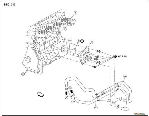
- Intake manifold
- Cylinder block
- Clamp
- Water hose
- Water hose clip
- Water hose
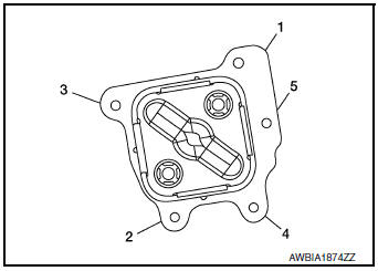
- Oil cooler
- Gasket
- Oil cooler relief valve
 Front
Front
Removal and Installation
WARNING: Be careful not to burn yourself, as engine oil and engine coolant may be hot.
NOTE: When removing components such as hoses, tubes/lines, etc., cap or plug openings to prevent fluid from spilling.
REMOVAL
- Drain engine coolant. Refer to CO-8, "Draining".
- Remove front air spoiler (RH). Refer to EXT-16, "Exploded View"
- Remove fender protector (RH). Refer to EXT-28, "FENDER PROTECTOR : Exploded View".
- Disconnect water hoses from the oil cooler.
- Remove oil cooler bolts in reverse numerical order.
- Remove oil cooler.
CAUTION:
- Be careful not to get burned when engine and engine oil may be hot.
- When removing, prepare a shop cloth to absorb any engine oil leaks or spillage.
- Completely wipe off any engine oil that adheres to engine and vehicle.
- Remove relief valve and O-ring, (if necessary).
INSTALLATION
Installation is in the reverse order of removal.
- Tighten oil cooler to specification as shown.
CAUTION:
- Do not reuse O-ring.
- Ensure O-ring and oil cooler sealing surface is free from dust, flaws, or deformation.
- Ensure water hose assembly is installed without kinks or areas of collapse.
- Replace relief valve, if removed.
Inspection
INSPECTION AFTER REMOVAL
Oil Cooler
Check oil cooler for cracks. Check oil cooler for clogging by blowing through engine coolant inlet. If necessary, replace oil cooler.
Relief valve
Inspect relief valve for movement, cracks, and breaks by pushing the ball. If replacement is necessary, remove the valve by prying it out using a suitable tool. Install a new valve by tapping it in place.
INSPECTION AFTER INSTALLATION
- Check the engine oil level and the engine coolant level and add engine oil and engine coolant. Refer to LU-7, "Inspection" and CO-8, "Inspection".
- Start the engine, and check that there are no leaks of engine oil or engine coolant.
- Stop the engine and wait for 5 minutes.
- Check the engine oil level and the engine coolant level again. Refer to LU-7, "Inspection" and CO-8, "Inspection".

 Oil pump
Exploded View
Front cover (Oil pump body united)
Outer rotor
Inner rotor
Oil pump cover
Regulator valve
Regulator valve spring
Regulator valve plug
CAUTION ...
Other materials:
U1000 CAN COMM CIRCUIT
Description
CAN communication allows a high rate of information transmission through the
two communication lines
(CAN-H line and CAN-L line) connecting various control units in the system. Each
control unit transmits/
receives data but selectively reads required data only.
DTC Logic
DTC DET ...
S connector circuit
Description
The starter motor magnetic switch is supplied with power when the ignition
switch is turned to the START position
while the selector lever is in the P (Park) or N (Neutral) position.
Diagnosis Procedure
Regarding Wiring Diagram information, refer to STR-7, "Wiring Diagram" ...
Hill Descent Control System (if so equipped)
Hill Descent Control System
WARNING
Never rely solely on the hill descent
control system to control vehicle speed
when driving on steep downhill grades.
Always drive carefully and attentively
when using the hill descent control system
and decelerate the vehi ...
