Nissan Rogue Service Manual: Engine control system
Symptom Table
SYSTEM ÔÇö BASIC ENGINE CONTROL SYSTEM
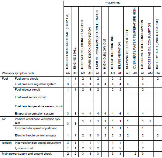
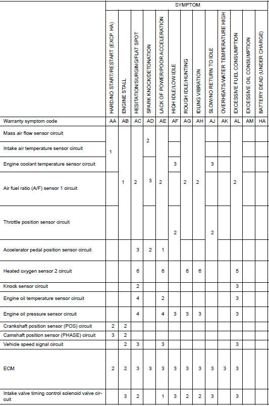
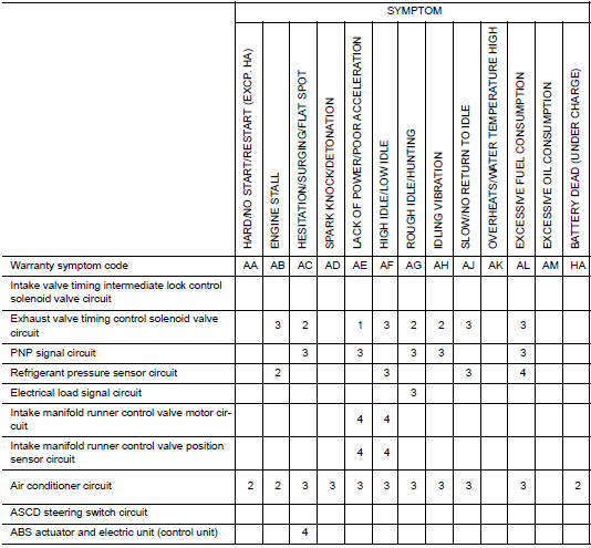
1 - 6: The numbers refer to the order of inspection.
(continued on next table)
SYSTEM ÔÇö ENGINE MECHANICAL & OTHER
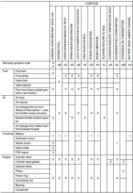
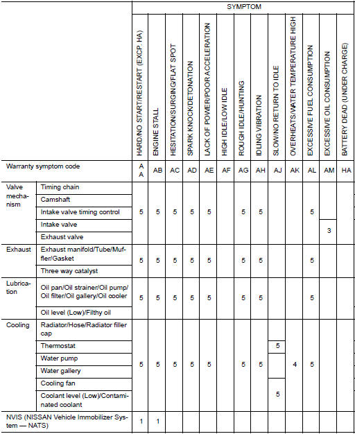
1 - 6: The numbers refer to the order of inspection.

 Information display is malfunctioning
Diagnosis Procedure
1.CHECK DTC WITH ECM
Check that DTC is not displayed.
Is the inspection result normal?
YES >> GO TO 2.
NO >> Perform trouble diagnosis relevant to DTC indicate ...
Other materials:
Door switch
WITH INTELLIGENT KEY
WITH INTELLIGENT KEY : Component Function Check
1.CHECK FUNCTION
Select "DOOR LOCK" of "BCM" using CONSULT.
Select "DOOR SW-DR", "DOOR SW-AS", "DOOR SW-RL", "DOOR SW-RR", in
"Data Monitor&quo ...
Bluetooth® streaming audio with Navigation
System
If you have a compatible Bluetooth® audio device
that is capable of playing audio files, the
device can be connected to the vehicleÔÇÖs audio
system so that the audio files on the device play
through the vehicleÔÇÖs speakers.
Connecting Bluetooth® audio
To connect your Bluetooth® audio ...
Connecting Procedure
Connecting Procedure
NOTE:
The connecting procedure must be performed
when the vehicle is stationary. If the
vehicle starts moving during the procedure,
the procedure will be cancelled.
Press the [ ] button
on the control
panel.
Touch the ÔÇťSettingsÔÇŁ key.
T ...
