Nissan Rogue Service Manual: Diagnosis system (BCM) (with intelligent key system)
COMMON ITEM
COMMON ITEM : CONSULT Function (BCM - COMMON ITEM)
APPLICATION ITEM
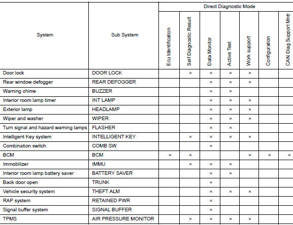
CONSULT performs the following functions via CAN communication with BCM.
|
Direct Diagnostic Mode |
Description |
| Ecu Identification | The BCM part number is displayed. |
| Self Diagnostic Result | The BCM self diagnostic results are displayed. |
| Data Monitor | The BCM input/output data is displayed in real time. |
| Active Test | The BCM activates outputs to test components. |
| Work support | The settings for BCM functions can be changed. |
| Configuration |
|
| CAN Diag Support Mnt | The result of transmit/receive diagnosis of CAN communication is displayed. |
SYSTEM APPLICATION
BCM can perform the following functions.
REAR DEFOGGER
REAR DEFOGGER : CONSULT Function (BCM - REAR DEFOGGER)
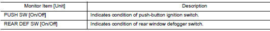
DATA MONITOR
ACTIVE TEST

WORK SUPPORT
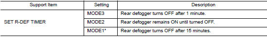
* : Initial setting
 System
System Description
SYSTEM DIAGRAM
OPERATION DESCRIPTION
When rear window defogger switch is turned ON while ignition
switch is ON, the rear window defogger
switch transmits rear w ...
 Diagnosis system (BCM) (without intelligent key system)
COMMON ITEM
COMMON ITEM : CONSULT Function (BCM - COMMON ITEM)
APPLICATION ITEM
CONSULT performs the following functions via CAN communication with BCM.
Direct Diagnostic Mode
De ...
Other materials:
Component parts
Component Parts Location
Instrument lower panel LH
No.
Component
Function
1
Combination meter
The combination meter transmittes the following signal via CAN
communications
to the TCM.
SPORT mode switch signal
...
P0132 A/F sensor 1
DTC Description
DTC DETECTION LOGIC
To judge the malfunction, the diagnosis checks that the A/F signal computed
by ECM from the A/F sensor 1
signal is not inordinately high.
DTC No.
CONSULT screen terms
(Trouble diagnosis content)
DTC detecting condition
P0132
A/F S ...
Wiring diagram
POWER DOOR LOCK SYSTEM
Wiring Diagram
REMOTE KEYLESS ENTRY SYSTEM
Wiring Diagram
...
