
Nissan Rogue Service Manual: Diagnosis and repair work flow
Work Flow
DETAILED FLOW
1.INTERVIEW FROM THE CUSTOMER
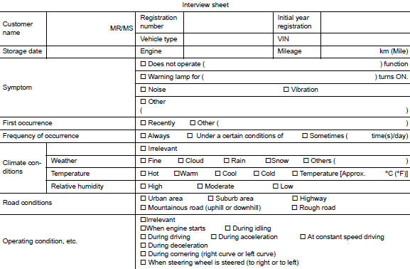
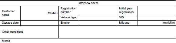
Clarify customer complaints before inspection. First of all, perform an interview utilizing BRC-67, "Diagnostic Work Sheet" and reproduce the symptom as well as fully understand it. Ask customer about his/her complaints carefully. Check symptoms by driving vehicle with customer, if necessary.
CAUTION: Customers are not professional. Never guess easily like “maybe the customer means that...,� or “ maybe the customer mentions this symptom�. >> GO TO 2.
2.CHECK SYMPTOM
Reproduce the symptom that is indicated by the customer, based on the information from the customer obtained by interview. Also check that the symptom is not caused by fail-safe mode. Refer to BRC-51, "Fail- Safe".
CAUTION: When the symptom is caused by normal operation, fully inspect each portion and obtain the understanding of customer that the symptom is not caused by a malfunction.
>> GO TO 3.
3.PERFORM THE SELF-DIAGNOSIS
 With CONSULT
- Turn the ignition switch OFF → ON.
CAUTION: Be sure to wait of 10 seconds after turning ignition switch OFF or ON.
- Repeat step 1 two or more times.
- Perform self-diagnosis for “ABS�.
Is DTC detected? YES >> Record or print self-diagnosis results and freeze frame data (FFD). GO TO 4.
NO >> GO TO 6.
4.RECHECK THE SYMPTOM
 With CONSULT
- Erase self-diagnostic results for “ABS�.
- Turn the ignition switch OFF → ON → OFF.
CAUTION: Be sure to wait of 10 seconds after turning ignition switch OFF or ON.
- Perform DTC confirmation procedures for the error-detected system.
NOTE: If some DTCs are detected at the some time, determine the order for performing the diagnosis based on BRC-54, "DTC Inspection Priority Chart". Is any DTC detected? YES >> GO TO 5.
NO >> Check harness and connectors based on the information obtained by interview. Refer to GI-41, "Intermittent Incident".
5.REPAIR OR REPLACE ERROR-DETECTED PART
- Repair or replace error-detected parts.
- Reconnect part or connector after repairing or replacing.
- When DTC is detected, erase self-diagnostic result for “ABS�.
CAUTION:
- Turn the ignition switch OFF → ON → OFF after erase self-diagnosis result.
- Be sure to wait of 10 seconds after turning ignition switch OFF or ON.
>> GO TO 7.
6.IDENTIFY ERROR-DETECTED SYSTEM BY SYMPTOM DIAGNOSIS
Estimate error-detected system based on symptom diagnosis and perform inspection.
Can the error-detected system be identified? YES >> GO TO 7.
NO >> Check harness and connectors based on the information obtained by interview. Refer to GI-41, "Intermittent Incident".
7.FINAL CHECK
With CONSULT
- Check the reference value for “ABS�.
- Recheck the symptom and check that the symptom is not reproduced on the same conditions.
Is the symptom reproduced? YES >> GO TO 3.
NO >> Inspection End.
Diagnostic Work Sheet
Description
- In general, customers have their own criteria for a problem. Therefore, it is important to understand the symptom and status well enough by asking the customer about his/her concerns carefully. To systemize all the information for the diagnosis, prepare the interview sheet referring to the interview points.
- In some cases, multiple conditions that appear simultaneously may cause a DTC to be detected.
INTERVIEW SHEET SAMPLE
 Basic inspection
...
 Additional service when replacing abs actuator and electric
unit (control unit)
Additional service when replacing abs actuator and electric
unit (control unit)
Description
When replaced the ABS actuator and electric unit (control unit), perform
adjust the neutral position of steering
angle sensor. Refer to BRC-72, "Work Procedure".
...
Other materials:
Troubleshooting guide
Verify the location of all Intelligent Keys that are
programmed for the vehicle. If another Intelligent
Key is in range or inside the vehicle, the vehicle
system may respond differently than expected.
Symptom
Possible Cause
Remedy
When stopping the engine
The Shift to Pa ...
Ducts and grilles
Exploded View
Side defroster duct (RH)
Defroster nozzle
Side defroster duct (LH)
Center ventilator duct
Heating and cooling unit assembly
Front foot duct (LH)
Front floor connecting duct (LH)
Front floor duct (LH)
Rear center ventilator duct
Adaptor duct 11 ...
Component parts
Component Parts Location
Steering column assembly
No.
Component
Function
1
ABS actuator and electric unit (control unit)
Transmits the following signal to EPS control unit via CAN
communication.
Vehicle speed signal (ABS)
...
