
Nissan Rogue Service Manual: Condenser
Removal and Installation
REMOVAL
- Partially lower headlining (rear). Refer to INT-30, "Removal and Installation".
- Disconnect the harness connectors from the condenser.
- Remove the bolt (A) and the condenser (1).
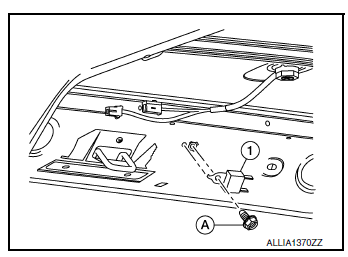
INSTALLATION
Installation is in the reverse order of removal.
 Filament
Inspection and Repair
INSPECTION
When measuring voltage, wrap tin foil around the top of the
negative
probe. Then press the foil against the wire with your finger.
Attach pro ...
 Horn
Horn
...
Other materials:
CAN system (type 8)
MAIN LINE BETWEEN IPDM-E AND DLC CIRCUIT
Diagnosis Procedure
1.CHECK CONNECTOR
Turn the ignition switch OFF.
Disconnect the battery cable from the negative terminal.
Check the following terminals and connectors for damage, bend and
loose connection (connector side
an ...
P1212 TCS communication line
Description
This CAN communication line is used to control the smooth engine operation
during the TCS operation. Pulse
signals are exchanged between ECM and “ABS actuator and electric unit (control
unit)�.
Be sure to erase the malfunction information such as DTC not only for “ABS
ac ...
Power supply and ground circuit
WITH INTELLIGENT KEY SYSTEM
WITH INTELLIGENT KEY SYSTEM : Diagnosis Procedure
Regarding Wiring Diagram information, refer to BCS-50, "Wiring Diagram".
1. CHECK FUSE
Check that the following fuse is not blown.
Terminal No.
Signal name
Fuse No.
161
BCM power sup ...
