Nissan Rogue Service Manual: Compression pressure
CHECKING COMPRESSION PRESSURE
- Warm up the engine to full operating temperature.
- Release the fuel pressure. Refer to EC-144, "Work Procedure".
- Remove the ignition coil and spark plug from each cylinder. Refer to EM-36, "Removal and Installation" and EM-17, "Removal and Installation".
- Connect engine tachometer (not required in use of CONSULT).
- Disconnect the fuel injector harness connector to avoid any residual fuel injection during the measurement.
- Install the compression tester with the adapter into the spark plug hole.
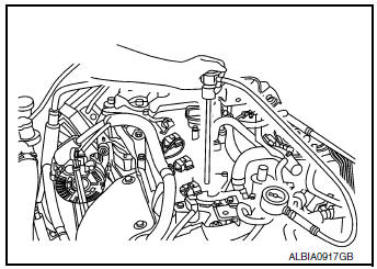
- Use compression tester whose end (a) (rubber portion) is smaller than 20 mm (0.79 in) in diameter. Otherwise, it may be caught by cylinder head during removal.

- With the accelerator pedal fully depressed, turn the ignition switch to the “START” position to crank over the engine. When the gauge pointer stabilizes, read the compression pressure and engine rpm. Perform these steps to check each cylinder.
CAUTION: Always use a fully charged battery to obtain specified engine cranking speed.
- If the engine speed is out of specified rpm range, check the battery. Check engine speed again with a fully charged battery.
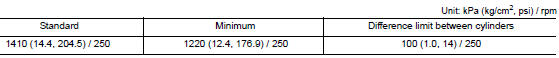
- If compression pressure is below minimum value, check valve
clearances and parts associated with combustion
chamber (valve, valve seat, piston, piston ring, cylinder bore, cylinder
head, cylinder head gasket).
After the checking, measure compression pressure again.
- If some cylinders have low compression pressure, pour small amount of engine oil into the spark plug hole of the cylinder to re-check it for compression.
- If the added engine oil improves the compression, the piston rings may be worn or damaged. Check the piston rings and replace if necessary.
- If the compression pressure remains at low level despite the
addition of engine oil, the valves may be malfunctioning.
Check the valves for damage. Replace the valve or valve seat accordingly.
- If two adjacent cylinders have respectively low compression pressure and their compression remains low even after the addition of engine oil, the head gasket is leaking. In such a case, replace the cylinder head gasket.
- Install spark plug, ignition coil and harness connectors. Refer to EM-17, "Removal and Installation".
 Camshaft valve clearance
Camshaft valve clearance
Perform this inspection as follows after removal, installation, or
replacement of the camshaft or any valve
parts, or if there are any unusual engine conditions due t ...

Other materials:
Service data and specifications (SDS)
Wheel Alignment (Unladen*1)
*1: Fuel, engine coolant, and lubricants are full. Spare tire, jack, hand
tools, and mats are in designated positions.
*2: Since an adjustment mechanism is not included, the value of the left and
right wheels must be used as the standard value.
Wheelarch Height ...
Navigation System voice commands
The following voice commands are available for
the Navigation System:
Street Address (address)
Points of Interest (name)
POI by Category
Home
Address Book
Previous Destinations
Enter Address in Steps
Cancel Route
For additional in ...
Towing your vehicle
When towing your vehicle, all jurisdictional and
local regulations for towing must be followed.
Incorrect towing equipment could damage your
vehicle. Towing instructions are available from a
NISSAN dealer. Local service operators are generally
familiar with the applicable laws and procedures
...
