Nissan Rogue Service Manual: Component parts
METER SYSTEM
METER SYSTEM : Component Parts Location
 Vehicle front
- View of the fuel pump and fuel level sensor inspection hole covers with the rear seat removed.
- View of front engine assembly
|
No. |
Component |
Function |
| 1 | Combination meter | Refer to MWI-8, "METER SYSTEM : System Description". |
| 2 | Steering switch | Refer to MWI-18, "Switch Name and Function". |
| 3 | Meter control switch | Refer to MWI-18, "Switch Name and Function". |
| 4 | Fuel level sensor unit (sub) | Transmits the fuel level sensor signal to the combination meter. |
| 5 | Fuel level sensor unit (main) | Transmits the fuel level sensor signal to the combination meter |
| 6 | Seat belt buckle switch LH | Transmits the seat belt buckle switch signal LH to the combination meter. |
| 7 | ABS actuator and electric unit (control unit) |
|
| 8 | Engine oil pressure sensor | Transmits the engine oil pressure sensor signal to the ECM. |
| 9 | Washer fluid level switch |
|
| 10 | Ambient sensor |
|
| 11 | ECM |
|
| 12 | TCM |
|
| 13 | BCM |
|
| 14 | Parking brake switch | Transmits the parking brake switch signal to the combination meter. |
METER SYSTEM : Design
ARRANGEMENT OF COMBINATION METER
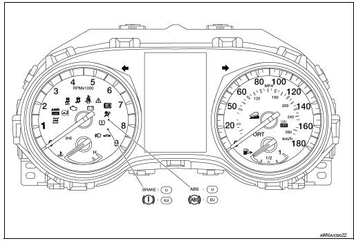
U: USA
EU: Except USA

 System
METER SYSTEM
METER SYSTEM : System Description
SYSTEM DIAGRAM
Combination Meter Input Signal (CAN Communication Signal)
DESCRIPTION
Combination Meter
The combination meter c ...
Other materials:
Connector Symbols
Most of connector symbols in wiring diagrams are shown from the terminal
side.
Connector symbols shown from the terminal side are enclosed by
a single line and followed by the direction mark.
Connector symbols shown from the harness side are enclosed by
a double line and foll ...
C1729 vehicle speed signal
DTC Logic
NOTE:
The Signal Tech II Tool [- (J-50190)] can be used to perform the following
functions. Refer to the Signal Tech II
User Guide for additional information.
Activate and display TPMS sensor IDs
Display tire pressure reported by the TPMS sensor
Read TPMS DTC ...
Washer level switch signal circuit
Description
Transmits the washer fluid level switch signal to the combination meter.
Diagnosis Procedure
Regarding Wiring Diagram information, refer to MWI-32, "Wiring Diagram".
1.CHECK WASHER FLUID LEVEL SWITCH SIGNAL CIRCUIT
Turn ignition switch OFF.
Disconnect comb ...
