Nissan Rogue Service Manual: C1155 brake fluid level switch
DTC Logic
DTC DETECTION LOGIC
| DTC | Display Item | Malfunction detected condition | Possible causes |
| C1155 | BR FLUID LEVEL LOW | When brake fluid level low signal is detected |
|
DTC CONFIRMATION PROCEDURE
1.CHECK SELF-DIAGNOSTIC RESULT
 With CONSULT.
- Turn ignition switch OFF to ON and wait 1 minute or more.
- Perform self-diagnostic result.
Is DTC C1155 detected? YES >> Proceed to diagnosis procedure. Refer to BRC-99, "Diagnosis Procedure".
NO >> Inspection End.
Diagnosis Procedure
Regarding Wiring Diagram information, refer to BRC-57, "Wiring Diagram".
1.CHECK BRAKE FLUID LEVEL
- Turn the ignition switch OFF.
- Check brake fluid level. Refer to BR-8, "Inspection".
Is the inspection result normal? YES >> GO TO 2.
NO >> Refill brake fluid. Refer to BR-16, "Drain and Refill".
2.CONNECTOR INSPECTION
- Turn ignition switch OFF.
- Disconnect combination meter connector M76 and brake fluid level switch connector E63.
- Check connectors and terminals for deformation, disconnection, looseness or damage.
Is the inspection result normal? YES >> GO TO 3.
NO >> Repair or replace as necessary.
3.CHECK BRAKE FLUID LEVEL SWITCH
Check brake fluid level switch. Refer to BRC-100, "Component Inspection".
Is the inspection result normal? YES >> GO TO 4.
NO >> Replace reservoir tank. Refer to BR-28, "Disassembly and Assembly".
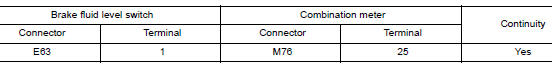
4.CHECK BRAKE FLUID LEVEL SWITCH CIRCUIT
- Turn the ignition switch OFF.
- Disconnect brake fluid level switch harness connector.
- Disconnect combination meter harness connector.
- Check continuity between brake fluid level switch harness connector and combination meter harness connector.
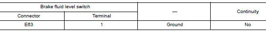
- Check continuity between brake fluid level switch harness connector and ground.
Is the inspection result normal? YES >> GO TO 5.
NO >> Repair or replace malfunctioning components.
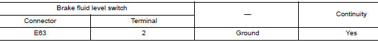
5.CHECK BRAKE FLUID LEVEL SWITCH GROUND CIRCUIT
Check continuity between brake fluid level switch harness connector and ground.
Is the inspection result normal? YES >> GO TO 6.
NO >> Repair or replace malfunctioning components.
6.CHECK COMBINATION METER
Check if indication and operation of combination meter are normal. Refer to MWI-8, "METER SYSTEM : System Description".
Is the inspection result normal? YES >> Replace ABS actuator and electric unit (control unit). Refer to BRC-136, "Removal and Installation".
NO >> Replace combination meter. Refer to MWI-82, "Removal and Installation".
Component Inspection
1.CHECK BRAKE FLUID LEVEL SWITCH
- Turn the ignition switch OFF.
- Disconnect brake fluid level switch harness connector.
- Check continuity between terminals of brake fluid level switch.

Is the inspection result normal? YES >> Inspection End.
NO >> Replace reservoir tank. Refer to BR-28, "Disassembly and Assembly".
 C1144 incomplete steering angle sensor adjustment
DTC Logic
DTC DETECTION LOGIC
DTC
Display Item
Malfunction detected condition
Possible causes
C1144
ST ANG SEN SIGNAL
When neutral position adjustment of steering angl ...
 C1160 DECEL G SEN SET
DTC Logic
DTC DETECTION LOGIC
DTC
Display Item
Malfunction detected condition
Possible causes
C1160
DECEL G SEN SET
When calibration of yaw rate/side/decel G sensor is ...
Other materials:
Steering wheel turning force is heavy or light
Description
Steering wheel turning force is heavy or light.
Diagnosis Procedure
1.PERFORM SELF-DIAGNOSIS
With CONSULT
Turn the ignition switch OFF to ON.
Perform “EPS” self-diagnosis.
Is any DTC detected?
YES >> Check the DTC. Refer to STC-13, "DTC Index" ...
Front wiper does not operate
Description
The front wiper does not operate under any operation conditions.
Diagnosis Procedure
Regarding Wiring Diagram information, refer to WW-22, "Wiring Diagram".
1. CHECK WIPER RELAY OPERATION
CONSULT ACTIVE TEST
Select FR WIPER of BCM (WIPER) active test item.
&nb ...
P0125 ECT sensor
DTC Description
DTC DETECTION LOGIC
DTC No.
CONSULT screen terms
(Trouble diagnosis content)
DTC detecting condition
P0125
ECT SENSOR
(Insufficient coolant temperature for closed
loop fuel control)
Voltage sent to ECM from the sensor is not practical, ...
