Nissan Rogue Service Manual: Air cleaner and air duct
Exploded View
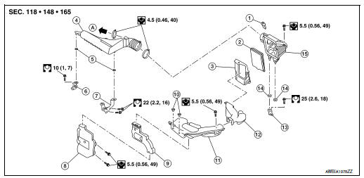
- Mass air flow sensor
- Air cleaner filter
- Air cleaner case (lower)
- Air duct assembly
- Grommet
- Resonator bracket (front)
- Resonator bracket (rear)
- Resonator
- Air duct
- Mounting clip
- Air duct assembly
- Air cleaner case duct
- Air cleaner bracket
- Grommet
- Air cleaner case (upper)
- To Electric throttle control actuator
Removal and Installation
REMOVAL
NOTE: Mass air flow sensor is removable under the car-mounted condition.
- Remove cowl top extension. Refer to EXT-25, "Removal and Installation".
- Remove air cleaner filter. Refer to EM-16, "Removal and Installation".
- Remove air duct assembly from air cleaner case (lower).
- Remove air cleaner case (lower).
- Disconnect harness connector from mass air flow sensor.
- Remove air cleaner case (upper).
- Remove mass air flow sensor from air cleaner case (upper) (if necessary).
- Separate air cleaner case duct from air cleaner case (lower) and air duct assembly.
- Remove air duct from air duct assembly and resonator.
- Remove resonator.
INSTALLATION
Installation is in the reverse order of removal.
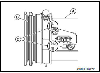
- Align mating marks (C) of air duct assembly (B) with air cleaner case (upper) (A) as shown.
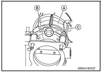
- Align mating marks (C) of air duct assembly (A) with electric throttle control actuator (B) as shown.
Inspection
INSPECTION AFTER REMOVAL
Inspect air duct and resonator assembly for cracks or tears.
- If anything found, replace air duct and resonator assembly.

 Intake manifold
Exploded View
Intake manifold
Intake manifold gasket
Electirc throttle control actuator O-ring
Electric throttle control actuator
Removal and Installation
REMOVAL ...
Other materials:
Component parts
METER SYSTEM
METER SYSTEM : Component Parts Location
Vehicle front
View of the fuel pump and fuel level
sensor inspection hole covers with
the rear seat removed.
View of front engine assembly
No.
Component
Function
1
Combination me ...
System description
COMPONENT PARTS
Component Parts Location
Center of back door
No.
Component
Function
1
Rod antenna
Refer to AV-14, "Rod Antenna, Antenna Amp., Satellite
Antenna and Antenna Feeder".
2
Antenna base (antenna amp. and sa ...
Rear-facing child restraint installation using the seat belts
Rear-facing child restraint installation using the seat belts
WARNINGThe three-point seat belt with Automatic
Locking Retractor (ALR) must be used
when installing a child restraint. Failure to
use the ALR mode will result in the child
restraint not being properly secured. The ...
