Nissan Rogue Service Manual: Additional service when replacing transaxle assembly
Description
Perform the following work after the transaxle assembly is replaced.
WRITING TCM DATA
- TCM performs accurate control by retrieving data (inherent characteristic value) of each solenoid. For this reason, after replacing transaxle assembly, it is necessary to write new data in TCM.
ERASING OF CVT FLUID DEGRADATION LEVEL DATA
- TCM records the degradation level of the CVT fluid calculated from the vehicle driving status. Therefore, if the transaxle assembly is replaced, it is necessary to erase the CVT fluid degradation level data recorded by TCM.
Work Procedure
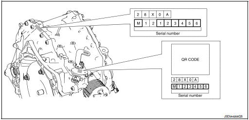
1.CHECK THE SERIAL NUMBER
Write down the serial number of new transaxle assembly.
>> GO TO 2.
2.WRITE TCM DATA (IP CHARACTERISTICS VALUE)
NOTE: Write data of new solenoid in TCM according to the following instructions:
 With CONSULT
CAUTION: When the work is interrupted, obtain data again from the supplied CD.
- Shift the selector lever to the P position.
- Turn ignition switch OFF and wait for 10 seconds.
- Turn ignition switch ON.
- Insert the supplied CD into CONSULT.
- Select “Work Support” in “TRANSMISSION”.
- Select “WRITE IP CHARA - REPLACEMENT AT/CVT”.
- Check that the serial number displayed on CONSULT screen and those written in the memo agree.
- Write data in TCM according to the instructions on the CONSULT screen.
NOTE: When writing is complete, the shift position indicator of the combination meter displays P.
>> GO TO 3.
3.ERASE CVT FLUID DEGRADATION LEVEL DATA
With CONSULT
- Select “WORK SUPPORT” in “TRANSMISSION”.
- Select “CONFORM CVTF DETERIORTN”.
- Touch “Clear”.
>> WORK END
 Additional service when replacing TCM
Description
Always perform the following items when the TCM is replaced.
TCM PROGRAMMING
Since vehicle specifications are not yet written in a new TCM, it
is necessary to write them w ...
 Additional service when replacing TCM and transaxle assembly
Description
When replacing TCM and transaxle assembly simultaneously, perform the
following work.
TCM PROGRAMMING
Since vehicle specifications are not yet written in a new TCM, it
i ...
Other materials:
Parking brake switch signal circuit
Component Function Check
1.CHECK PARKING BRAKE SWITCH OPERATION
Check that brake warning lamp in combination meter turns ON/OFF when parking
brake is actuated.
Is the inspection result normal?
YES >> Inspection End.
NO >> Proceed to diagnosis procedure. Refer to WCS-45, " ...
Vehicle Dynamic Control (VDC) system
The Vehicle Dynamic Control (VDC) system uses
various sensors to monitor driver inputs and vehicle
motion. Under certain driving conditions,
the VDC System helps to perform the following
functions:
Controls brake pressure to reduce wheel
slip on 1 slipping drive wheel so power is
t ...
Radiator
Exploded View
REMOVAL
Reservoir tank
Reservoir tank cap
Reservoir tank hose
Mounting rubber (upper)
Radiator cap
Radiator
CVT fluid cooler hose
Clamp
CVT fluid cooler hose
Mounting rubber (lower)
O-ring
Drain plug
...
