Nissan Rogue Service Manual: Structure and operation
Positive Crankcase Ventilation
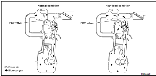
This system returns blow-by gas to the intake manifold.
The positive crankcase ventilation (PCV) valve is provided to conduct crankcase blow-by gas to the intake manifold.
During partial throttle operation of the engine, the intake manifold sucks the blow-by gas through the PCV valve.
Normally, the capacity of the valve is sufficient to handle any blow-by and a small amount of ventilating air.
The ventilating air is then drawn from the air inlet tubes into the crankcase. In this process the air passes through the hose connecting air inlet tubes to rocker cover.
Under full-throttle condition, the manifold vacuum is insufficient to draw the blow-by flow through the valve.
The flow goes through the hose connection in the reverse direction.
On vehicles with an excessively high blow-by, the valve does not meet the requirement. This is because some of the flow will go through the hose connection to the air inlet tubes under all conditions.
On Board Refueling Vapor Recovery (ORVR)
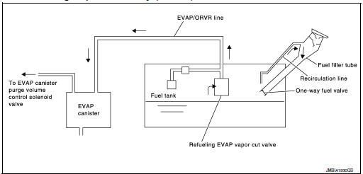
From the beginning of refueling, the air and vapor inside the fuel tank go through refueling EVAP vapor cut valve and EVAP/ORVR line to the EVAP canister. The vapor is absorbed by the EVAP canister and the air is released to the atmosphere.
When the refueling has reached the full level of the fuel tank, the refueling EVAP vapor cut valve is closed and refueling is stopped because of auto shut-off. The vapor which was absorbed by the EVAP canister is purged during driving.
WARNING:
When conducting inspections below, be sure to observe the following:
- Put a “CAUTION: FLAMMABLE” sign in workshop.
- Do not smoke while servicing fuel system. Keep open flames and sparks away from work area.
- Be sure to furnish the workshop with a CO2 fire extinguisher.
CAUTION:
- Before removing fuel line parts, carry out the following procedures:
- Put drained fuel in an explosion-proof container and put lid on securely.
- Release fuel pressure from fuel line. Refer to EC-144, "Work Procedure".
- Disconnect battery ground cable.
- Always replace O-ring when the fuel gauge retainer is removed.
- Do not kink or twist hose and tube when they are installed.
- Do not tighten hose and clamps excessively to avoid damaging hoses.
- After installation, run engine and check for fuel leaks at connection.
- Do not attempt to top off the fuel tank after the fuel pump
nozzle shuts off automatically.
Continued refueling may cause fuel overflow, resulting in fuel spray and possibly a fire.
 Component parts
Component Parts Location
ENGINE ROOM COMPARTMENT
No.
Component
Function
1
IPDM E/R
IPDM E/R control the internal relays and the actuators.
Refer ...
 System
ENGINE CONTROL SYSTEM
ENGINE CONTROL SYSTEM : System Description
SYSTEM DIAGRAM
SYSTEM DESCRIPTION
ECM controls the engine by various functions.
Function
Reference
Multipor ...
Other materials:
Both doors mirror defogger don’t operate but rear window defogger operates
Diagnosis Procedure
Regarding Wiring Diagram information, refer to DEF-12, "Wiring Diagram".
1. CHECK DOOR MIRROR DEFOGGER FUSE
Check if the following fuse in fuse block (J/B) is blown.
Is the inspection result normal?
YES >> GO TO 2.
NO >> Replace the blown fuse af ...
Stall test
Work Procedure
INSPECTION
Check the engine oil level. Replenish if necessary. Refer to LU-7,
"Inspection".
Check for leak of the CVT fluid. Refer to TM-190, "Inspection".
Drive for about 10 minutes to warm up the vehicle so that the CVT
fluid temp ...
Recommended chemical products
and sealants
Refer to the following chart for help in selecting the appropriate chemical
product or sealant.
Product Description
Purpose
NISSAN North America
Part No. (USA)
NISSAN Canada Part
No. (Canada)
Aftermarket Crossreference
Part Nos.
1
Rear View Mirror ...
