Nissan Rogue Service Manual: P0743 torque converter
DTC Description
DTC DETECTION LOGIC
| DTC | CONSULT screen terms (Trouble diagnosis content) | DTC detection condition |
| P0743 | TORQUE CONVERTER (Torque Converter Clutch Circuit Electrical) | When all of the following conditions are satisfied and this state is
maintained
for 0.48 seconds:
|
POSSIBLE CAUSE
- Harness or connector (Torque converter clutch solenoid valve circuit is shorted to ground)
- Torque converter clutch solenoid valve
FAIL-SAFE
- Start is slow
- Acceleration is slow
- Lock-up is not performed
DTC CONFIRMATION PROCEDURE
CAUTION: Be careful of the driving speed.
1.PREPARATION BEFORE WORK
If another "DTC CONFIRMATION PROCEDURE" occurs just before, turn ignition switch OFF and wait for at least 10 seconds, then perform the next test.
>> GO TO 2.
2.PREPARATION BEFORE OPERATION
 With CONSULT
- Start the engine.
- Select ÔÇťData MonitorÔÇŁ in ÔÇťTRANSMISSIONÔÇŁ.
- Select ÔÇťFLUID TEMPÔÇŁ.
- Confirm that the CVT fluid temperature is in the following range.
FLUID TEMP : 20┬░C (68┬░F) or more
 With GST
- Start the engine.
- Set the CVT fluid to 20┬░C (68┬░F) or more.
NOTE: When the ambient temperature is 20┬░C (68┬░F), the CVT fluid usually increases to 50 to 80┬░C (122 to 176┬░F) with driving in an urban area for approximately 10 minutes. Is the CVT fluid 20┬░C (68┬░F) or more? YES >> GO TO 3.
NO >> 1. Warm the transaxle.
2. GO TO 3.
3.CHECK DTC DETECTION
- Drive the vehicle.
- Maintain the following conditions for 10 seconds or more.
Selector lever : ÔÇťDÔÇŁ position
Vehicle speed : 40 km/h (25 MPH) or more
- Stop the vehicle.
- Check the first trip DTC.
Is ÔÇťP0743ÔÇŁ detected? YES >> Go to TM-134, "Diagnosis Procedure".
NO-1 >> To check malfunction symptom before repair: Refer to GI-41, "Intermittent Incident".
NO-2 >> Confirmation after repair: INSPECTION END
Diagnosis Procedure
1.CHECK CIRCUIT BETWEEN TCM AND CVT UNIT
- Turn ignition switch OFF.
- Disconnect TCM connector and CVT unit connector.
- . Check continuity between TCM harness connector terminal and ground.

Is the inspection result normal? YES >> GO TO 2.
NO >> Repair or replace malfunctioning parts.
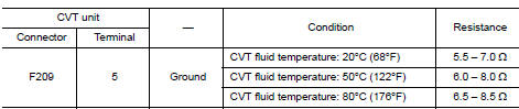
2.CHECK CIRCUIT BETWEEN CVT UNIT AND GROUND
Check resistance between CVT unit harness connector terminal and ground.
Is the inspection result normal? YES >> INSPECTION END
NO >> There is malfunction of torque converter clutch solenoid valve. Replace transaxle assembly. Refer to TM-220, "Removal and Installation".
 P0740 torque converter
DTC Description
DTC DETECTION LOGIC
DTC
CONSULT screen terms
(Trouble diagnosis content)
DTC detection condition
P0740
TORQUE CONVERTER
(Torque Converter Clutch Circui ...
 P0744 torque converter
DTC Description
DTC DETECTION LOGIC
DTC
CONSULT screen terms
(Trouble diagnosis content)
DTC detection condition
P0744
TORQUE CONVERTER
(Torque converter clutch circui ...
Other materials:
Maximum load limits
Never allow the total trailer load to exceed the
value specified in the ÔÇťTowing
Load/SpecificationÔÇŁ chart found in this section.
The total trailer load equals trailer weight plus its
cargo weight.
The maximum Gross Combined Weight Rating
(GCWR) should not exceed the value specified
in ...
Throttle valve closed position learning
Description
Throttle Valve Closed Position Learning is a function of ECM to learn the
fully closed position of the throttle
valve by monitoring the throttle position sensor output signal. It must be
performed each time the harness connector
of the electric throttle control actuator or ECM is ...
System
ENGINE CONTROL SYSTEM
ENGINE CONTROL SYSTEM : System Description
SYSTEM DIAGRAM
SYSTEM DESCRIPTION
ECM controls the engine by various functions.
Function
Reference
Multiport fuel injection system
EC-34, "MULTIPORT FUEL INJECTION SYSTEM : System Description
(wit ...
