Nissan Rogue Owners Manual: Active trace control
This system senses driving based on the driver’s steering and acceleration/braking patterns, and controls brake pressure at individual wheels to aid tracing at corners and help smooth vehicle response.
The Active Trace Control can be set to ON (enabled) or OFF (disabled) through the Vehicle Information Display “Settings” page. For additional information, refer to “Vehicle Information Display” in the “Instruments and Controls” section of this manual.
When the VDC OFF switch is used to turn off the VDC system, the Active Trace Control is also turned off.
Active trace control
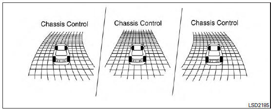
When the Active Trace Control is operated and the “Chassis Control”mode is selected in the trip computer, the Active Trace Control graphics are shown in the vehicle information display. For additional information, refer to “Trip Computer” in the “Instruments and Controls” section of this manual.
If the chassis control warning message appears in the vehicle information display, it may indicate that the Active Trace Control is not functioning properly. Have the system checked by a NISSAN dealer as soon as possible
| WARNING The active trace control may not be effective depending on the driving condition. Always drive carefully and attentively. |
When the Active Trace Control is operating, you may feel a pulsation in the brake pedal and hear a noise. This is normal and indicates that the active trace control is operating properly.
Even if the Active Trace Control is set to OFF, some functions will remain on to assist the driver (for example: avoidance scenes).
 Chassis Control
The chassis control is an electric control module
that includes the following functions:
Active Trace Control
Active Engine Brake
Active Ride Control
...
 Active engine brake
The Active Engine Brake function adds subtle
deceleration by controlling CVT gear ratio, depending
on the cornering condition calculated
from driver’s steering input and plural sensors.
This b ...
Other materials:
Cluster lid C
Exploded View
Audio unit (AUDIO WITHOUT BOSE) /
AV control unit (AUDIO WITH BOSE)
(NAVIGATION WITH BOSE)
A/C switch assembly (AUTOMATIC
AIR CONDITIONING) / front air control
(MANUAL AIR CONDITIONING)
Cluster lid C
Removal and Installation
REMOVAL
Release ...
Removal and installation
FRONT AIR CONTROL
Removal and Installation
REMOVAL
Release the front air control clips and pawls using a suitable
tool.
: Metal clip
: Pawl
Disconnect the harness connector from the front air control (1)
and remove.
INSTALLATION
Installation is in the reverse order of ...
Glove box assembly and housing
Removal and Installation
REMOVAL
Release instrument side finisher (RH) (1) pawls using a suitable
tool and remove.
: Pawl
NOTE:
LH side shown; RH similar.
Release the glove box damper (1) from the glove box assembly
(2) as shown.
Release the glove box assembly pawls ...
